

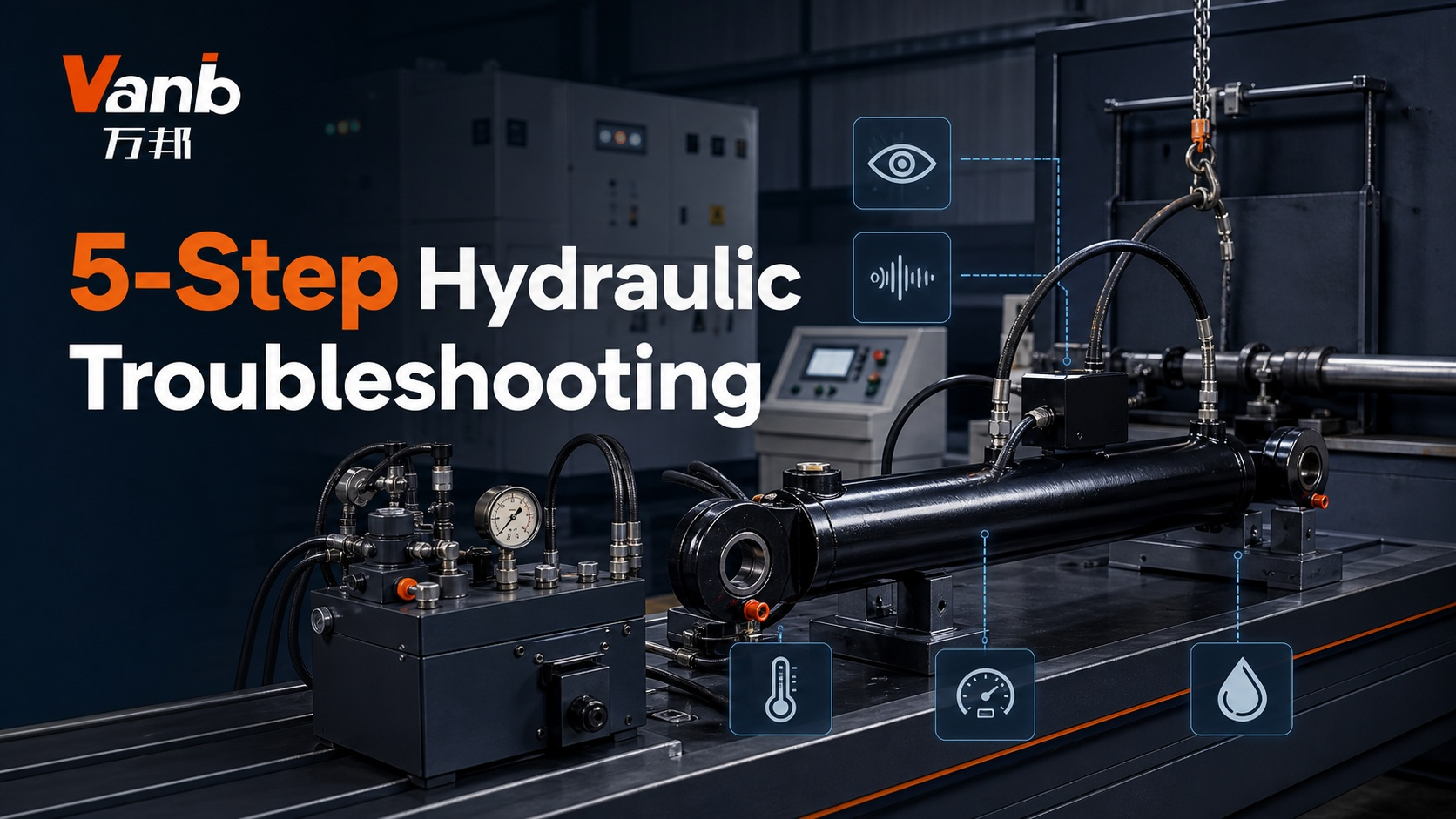
Safety Reminder: Never place your hands near moving parts, hot hydraulic components, or suspected high-pressure leaks. Before inspection, testing, or maintenance, shut down and isolate the equipment, secure any elevated load, release residual hydraulic pressure, and follow the machine manufacturer's lockout and maintenance procedures.
A Reliable Approach to Hydraulic System Troubleshooting
Hydraulic problems are often symptoms of issues occurring elsewhere in the circuit. For example, a cylinder that moves too slowly may be affected by restricted flow, insufficient pump output, a malfunctioning valve, internal leakage, excessive mechanical resistance, or incorrect hydraulic fluid. Likewise, abnormal pump noise does not necessarily mean that the pump itself has failed; air entering through the suction side can create similar symptoms.
For this reason, effective hydraulic troubleshooting should not begin with immediate component replacement. A better approach is to establish the normal operating condition, gather observable evidence, perform controlled measurements, and narrow down the fault systematically.
The five-step process below develops the traditional inspection sequence of observing, listening, checking heat and vibration, measuring system conditions, and evaluating fluid or odor into a more structured diagnostic method. The exact pressure, temperature, flow, viscosity, and vibration limits should always be taken from the relevant machine and component manufacturer's specifications.
Start by Clearly Identifying the Problem
Before testing individual components, establish exactly when and how the fault occurs.
· Note whether the issue appears during a cold start, after the system reaches operating temperature, in one particular direction, under load, during valve switching, or throughout operation.
· Determine which hydraulic functions are affected and whether the problem developed gradually or appeared suddenly.
· Check the maintenance history for recent hose replacement, filter changes, hydraulic oil changes, component adjustments, repairs, overload conditions, or possible contamination.
· Compare the current operating cycle, sound, pressure, temperature, and actuator performance with the machine's documented normal condition.
This initial information helps prevent unnecessary testing and gives subsequent measurements a clear operating context.
Step 1 — Inspect the Entire Hydraulic Circuit
Begin with the overall condition and configuration of the hydraulic system rather than focusing immediately on one component.
Check the pump, valves, cylinders or hydraulic motors, reservoir, filters, cooler, hoses, tubes, clamps, electrical connections, and mechanical load against the equipment documentation. Look for obvious abnormalities such as kinked hoses, disconnected lines, damaged protection, loose supports, scored cylinder rods, displaced seals, wet fittings, accumulated oil contamination, or replacement components that do not match the specified configuration.
The actuator's behavior can also provide useful diagnostic information. From a safe location, observe whether movement is slow, uneven, intermittent, unstable, or different between extension and retraction. Cylinder drift, creeping, hesitation, or inconsistent stopping may help identify which section of the circuit requires closer investigation.
The reservoir should also be checked through the designated sight glass or inspection point. Record abnormal conditions such as excessive foam, cloudiness, visible particles, sediment, unusual darkening, or a milky appearance. These observations are useful evidence, but fluid appearance alone should not be treated as a definitive diagnosis.
Step 2 — Use Operating Noise as a Diagnostic Clue
Every hydraulic machine has a characteristic operating sound. Establishing that baseline makes it easier to identify changes.
Listen for new whining, rattling, knocking, chatter, or impact sounds. Determine whether the noise remains constant, follows a repeating pattern, changes with system load, or occurs only when a valve changes position.
If safe to do so, identify the general area where the sound originates, such as the pump, motor, valve manifold, piping, cylinder, or mechanical mechanism. Do not enter a hazardous area simply to locate a sound.
A sharp pump whine or rough, gravel-like noise can be associated with suction-side restriction, air entrainment, or cavitation. Valve chatter may be related to unstable pressure control, contamination, incorrect adjustment, or an electrical control issue. Strong pipe vibration or impact during rapid actuator reversal may indicate pressure pulsation, inadequate pipe support, or abrupt valve transition.
Noise should be treated as an indication rather than proof of component failure. Confirm the suspected cause through appropriate measurements before removing or replacing parts.
Step 3 — Check Temperature, Vibration, and Actuator Behavior Without Direct Contact
Older troubleshooting practices sometimes involve touching a hydraulic component or pipe to estimate temperature, vibration, or leakage. This should not be used around high-pressure hydraulic equipment because surfaces may be hot, components may move unexpectedly, and pressurized fluid can cause serious injection injuries.
Instead, use non-contact equipment such as an infrared thermometer or thermal camera to monitor temperature. Where vibration analysis is necessary, use a suitable vibration meter or properly installed sensor. Mechanical fasteners and connections should only be inspected directly after the equipment has been shut down, isolated, depressurized, and any stored load has been safely supported.
Compare similar components and repeat operating cycles under consistent conditions. A localized temperature increase may indicate a restriction or excessive energy loss. Rising reservoir temperature may point toward abnormal heat generation. Increased pump vibration or cylinder stick-slip can provide additional clues about the source of the problem.
Never use your hand to search for a hydraulic leak. Even a small high-pressure leak can penetrate the skin and cause a hydraulic injection injury that requires immediate medical attention.
Step 4 — Confirm System Conditions with Pressure and Flow Tests
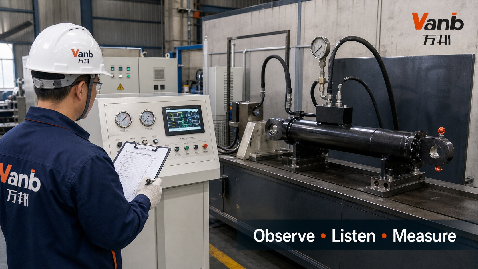
When visual and operational observations are insufficient, use properly rated and calibrated test instruments at the manufacturer's designated test points.
Depending on the circuit, relevant measurements may include pump outlet pressure, actuator-port pressure, pilot or control pressure, pressure drop across filters or valves, and return-line back pressure. Pump inlet conditions may require an appropriate vacuum or compound gauge rather than a standard pressure gauge.
Do not record pressure values without recording the conditions under which they were measured. Oil temperature, motor or engine speed, system load, valve position, actuator direction, and measurement time should also be documented. These details make the readings repeatable and easier to compare with the manufacturer's specifications.
It is also important to distinguish pressure from flow. A system may achieve the expected pressure while still delivering insufficient flow, resulting in slow actuator movement. Where necessary, use a controlled flow measurement or timed actuator cycle to determine whether the available flow meets the required operating condition.
Never increase or alter a relief-valve setting simply because the machine is showing a performance problem. First verify the specified setting and determine why the relief valve is opening.
Step 5 — Examine Hydraulic Fluid and Confirm the Repair
Fluid condition can provide important information when combined with other diagnostic evidence. An unusual burnt or sharp smell may be associated with overheating, fluid oxidation, incorrect oil mixing, contamination, or an electrical overheating event. However, odor alone is not sufficient to identify the fault.
Do not deliberately inhale hydraulic vapors or lean over an open reservoir to identify an odor. If the smell is accompanied by smoke, an electrical burning odor, or rapidly increasing temperature, stop the equipment and follow the site's emergency procedure.
Confirm that the hydraulic fluid currently in the machine matches the manufacturer's specified product. This is particularly important following commissioning, maintenance, or an oil change. Depending on the application, further checks may include oil sampling, cleanliness levels, water content, viscosity, filter condition, and service history.
Once corrective work has been completed, the system should be returned to its required operating condition. Restore guards, maintain system cleanliness, bleed or commission the circuit according to the manufacturer's procedure, and repeat the original controlled test. The repair should be considered successful only when the original symptom has been resolved and the system remains stable without introducing another fault.
A More Efficient Hydraulic Fault-Isolation Process
· Reproduce the fault only when the test can be performed under safe and controlled conditions.
· Refer to the hydraulic schematic to understand the relevant power path, control path, actuator, and return circuit.
· Start with basic checks such as fluid level, filter condition, visible damage, connectors, system settings, and operating conditions before disassembling components.
· Take measurements at defined test points and compare them with the values specified by the manufacturer rather than relying on generic industry assumptions.
· Modify only one condition at a time, record the result, and use the same controlled conditions to verify the final repair.
This approach reduces unnecessary component replacement and makes the troubleshooting process easier to document and repeat.
Situations That Require Immediate Shutdown
Hydraulic equipment should not continue operating when there is uncontrolled actuator movement, loss of load-holding capability, a damaged or bulging hose, pressurized fluid spray, smoke, a burning odor, rapidly increasing temperature, severe knocking, damaged protective guards, or measurements outside the manufacturer's specified safe operating range.
Continuing to operate a machine simply to gather additional diagnostic information can increase both equipment damage and personnel risk. When a serious abnormal condition is present, stop the machine and apply the required isolation procedure before further investigation.
Frequently Asked Questions
Can abnormal hydraulic noise identify the fault by itself?
No. Sound is useful for identifying where further investigation may be required, but it should be combined with pressure, flow, temperature, fluid condition, and circuit-performance data before determining the root cause.
Can I touch a hydraulic hose to check its temperature or find a leak?
Direct contact should be avoided when a component may be hot, pressurized, or moving. Use non-contact temperature measurement and approved leak-detection methods, and perform close inspection only after the equipment has been properly isolated and depressurized.
Why can a cylinder move slowly even when the pressure reading appears normal?
Pressure and flow describe different aspects of hydraulic operation. A system can reach the expected pressure while still having insufficient flow because of a restriction, inadequate pump delivery, internal leakage, reduced drive speed, or a control-system problem. A suitable flow or cycle-time test may therefore be necessary.
Reliable Hydraulic Solutions for Commercial and Engineering Applications
Reliable hydraulic performance depends not only on individual components but also on correct system configuration, safe maintenance practices, accurate diagnosis, and appropriate component selection. Vanb Hydraulic supplies hydraulic cylinders, hydraulic systems, and related components for commercial vehicles and engineering applications.
Explore product and application information at www.vanbhydraulic.com.
Authoritative References
· HSE high-pressure fluid injection hazards
· HSE hydraulic injection injury safety alert
· Parker hydraulic troubleshooting reference
Technical Note: ISO 4413:2010 remains current following its 2021 confirmation. Diagnostic methods, operating limits, and acceptable performance values should always be verified against the documentation provided by the specific machine, component, and hydraulic-fluid manufacturers.
www.vanbhydraulic.com
Hubei Wanbang Hydraulic Equipment Co., Ltd.